What is Impedance matching? Firstly, let us talk from the impedance. In electrical engineering, impedance is the ratio of voltage to current with the consideration of phase angle. As to the Ohm's law V= IR, where V – voltage (I is the current and R is the resistance of the network. ) In RF, the idea of impedance matching is to equalizing the source and load impedance for maximum power transfer. Impedance matching is to making source and load impedance as similar as possible in order to minimize losses.
Smith Chart
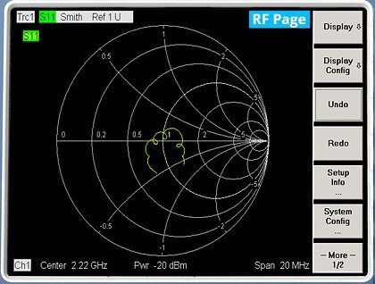
 It is is a chart representation of impedance and admittance grid , developed by Philip Smith in Bell’s radio research lab during 1930s. Since then Smith chart is widely popular among electrical and electronic network engineers to solve the problems and illustrate a complex network condition. Since the early stages of network analyzer, Smith Chart is one of the most important format to show the reflection of individual ports and easy to figure out mismatch in the network.
Purpose
Protecting the devices from reflection. In high power transmission system, any power reflection may cause severe damage to the amplifiers and other devices.
Maximizing power transfer from the transmitter to the load and increases the efficiency. At low power level, avoiding losing any signal is important and that requires perfect matched network.
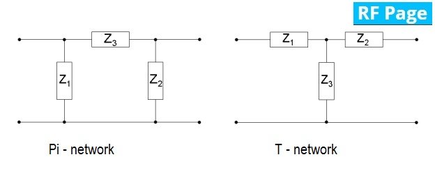
Matching networks: In network analysis, two most common matching networks are the Pi and T-network. The main idea is to get full control of the circuit's Q . In most of the cases, it is very useful where the design specifications are tighter and lesser option to implement. Pi and T-network offers the variety to handle different situations and optimize the network for Max efficiency. Most of common network impedance standard is 50 Ohm, another standard is 75 Ohm. To have a better matched network, we need to have all the components in the circuitry matched to 50 Ohm such as PCBs, connectors, cables etc. ICapacitors, nductors and impedance transformers are the most commonly components used for matching of network.
Q = f/BW: Q is the the network's quality factor, described as the ratio between the operating frequency (f) over the bandwidth (BW).
 Pi -networks are often used as a solution to match a high impedance source to lower load impedance and to match a low impedance source to higher impedance load. They are good for wide frequency range and impedance transformation.
T-networks are another common topology used for impedance matching, usually known as LLC circuits with combination of two inductors and capacitor in shunt. Conversion from a Pi-network to T-network is also possible and during some complex network analysis, it will be necessary.
Hoping our artical can help you get to know more about the impedance matching, any opinion welcome to discuss with us~